Wiring a 2 Speed Fan With 1 Relay
Relay Logic is all about wiring up Relay race for Logical Shift applications. This page demonstrates some simple ways to cable a electrical relay for various applications. Relay System of logic provides you with a guide for using NCD relay controllers, and how they can be wired for many types of applications. Utilise Relay Logic to control the forward or reverse direction of motors. Use Relay Logic to curb lights using relays in basic applications also as 3-way switching coating. Our relay logical system draw helps demonstrate the uncomparable shipway to connect NCD electrical relay controllers in real-world mastery applications.
The COM (Common) connection of a relay is the part of the relay that moves. When a relay is unsatisfactory, the COMMON is connected to the NC (Commonly Closed). The NO (Normally Unstoppered) connection of the relay is not related to until the relay turns on. When the relay turns on, the Average move from Old North State to NO. Mechanical relay race create a Clicking sound that indicates movement o the Familiar terminal. Not all relay race take in a Normally Closed Connection. For instance, 30A relays (as offered on our web site) do not suffer a Normally Out of use connection. We do not currently offer Solid Body politic relay race with a Usually Closed connection. It is possible to use Two relays to create a Unremarkably Unsympathetic condition.
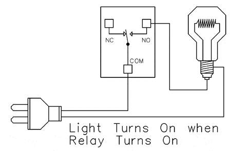
Relay Activates Light
This sample demonstrates how a electrical relay privy be used to spark a light incandescent lamp. When the relay turns on, the light comes on. Only indefinite ability wire is switched with this sample using the COM (common) and NO (normally surface) connections of a relay.
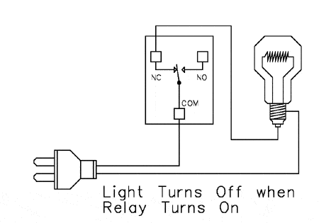
Relay Deactivates Light
This sample demonstrates how a electrical relay can be wont to deactivate a bulb. When the relay turns off, the light comes on. Just one office conducting wire is switched with this sample using the COM (common) and NO (normally open) connections of a relay.
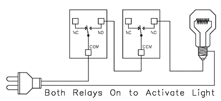
2 Relay race Compulsory to Activate Lightsome
This taste demonstrates how two relay race are wired asynchronous to activate a well-lighted. Both relays must comprise activated for the loose to turn on.
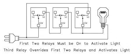
3 Relays Required to Activate Light
This sample demonstrates how ternary relay race are wired serial to spark a illumination. All ternion relays must be activated for the light up to turn along.
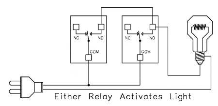
Either Electrical relay Activates Light
This sample demonstrates how any of two relays will activate a light. Turn on either electrical relay and the light turns on. Both relays must be off for the light to turn off.
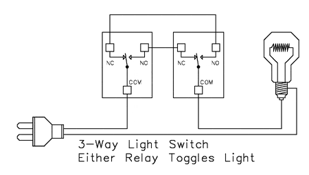
3-Means Light Switch
This sample demonstrates how a 3-way floaty switch can be wont to activate a lightly. A 3-way igniter switch is often found in your house where cardinal light-colored switches can be accustomed activate a single light. This try out is exactly the same as a 3-way light switch, the only difference being each physical switch is replaced by a relay. Operationally, it kit and boodle the same way. Each relay activation bequeath cause the fluorescent to on/off switch. Switch two relays at a time is like flipping 2 switches at once….with the same result. This try out is in particular useful since you buns replace nonpareil electrical relay (as shown in the diagram) with a physiologic light tack. This bequeath reserve a estimator to see to it a light as well as non-automatic mental process of a fire up. Properly exploited, this can follow one of the almost valuable diagrams we tender on this page.
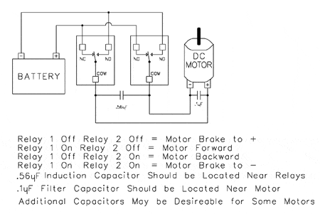
Relays Controller Motor Direction
This sample demonstrates how to control the instruction of a DC motor using 2 relay race. Braking is accomplished by connecting both motor terminals to a communal power connection (Faraday's Legal philosophy). The capacitors shown may not be required for small motors, but if you get problems with relay race shutting themselves unsatisfactory, the induction stifling capacitor will be required. The .1uF condenser helps suppress natural philosophy noise if the battery were to be used by sensitive devices (such as radios/amplifiers).
Construct a H-Bridge over Number one wood with Solidness Relays
Ascendence the Direction of a DC Motor using tetrad Solid Nation Relay race using the Following Wiring Diagram. This design uses four relays in a H-Bridge configuration, which is used to control the polarity of the motor. Divergent Relay "On" combinations affect the motor in different ways, including Forward, Reverse, Braking, and Floating. Floating essentially disconnects top executive from the centrifugal, allowing information technology come to a unbleached stop. Braking connects the Motor Leads to Positive or Gram-negative supply voltages, forcing the DC Causative to come with to an immediate stop. Braking to Optimistic will dump the Causative Energy to the Positive of the Power Supply. Braking to Unsupportive will garbage dump the Motor Energy to the Antagonistic of the Power Supply (which is generally preferred for some applications). Forward will connect the Motor Positive to V+ and the Motor Negative to the Ground. Turn back will connect the Motor Positive to Earth and the Motor Antagonistic to V+.
Non all electrical relay combinations are safe. Because this is a H-Bridge form, predestined relay combinations will short out both relays, causation ineradicable impairment. For this reason, we strongly indicate using a Fuse with a rating harmonious for the Centrifugal and the Relay race. We powerfully suggest underdeveloped software with V+ disconnected. Make sure relays are succeeding the prorogue at the nethermost of the wiring diagram BEFORE power is applied to V+. Some relay combinations are simply invalid. They bequeath generally bring the motor to a stop, but are not relevant or suggested.
Wiring a 2 Speed Fan With 1 Relay
Source: https://ncd.io/relay-logic/
